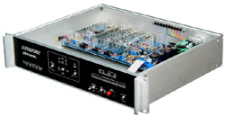
3031 Uplink Power Controller & Protection Switch
One output protected by two inputs (all connections 75 ohm); protection via remote or local control or automatically monitored loss of input or output power; optional up link power boost (up to 20 dB) controlled by satellite beacon receiver voltage (HPA compression compensation); 2 RU high; 100 to 130 VAC power supply
| Model 3031 Characteristics | |
| Channel Interfaces | |
| Dual Input Channels 1 and 2 Lineup Tone Input Single Output Channel 75 Channel 1 Minimum Gain: Channel 1 Maximum Gain: |
Inputs and Outputs: 75Ω unbalanced Inputs and Outputs: > 26 dB return loss Operating Frequency Range: 70 MHz ± 20 MHz Minimum Power Input: -20 dBm Maximum Power Output: +10 dBm 0 dB ± 0.1 dB 20 dB +1.0, -0.1 dB |
| Channel 1 gain is based upon satellite beacon receiver voltage. Voltage to gain relationship user defined. This Uplink Power Control feature can be disabled making Channel 1 fixed unity gain the same as Channel 2. |
|
| Channel 2 Gain (fixed): Amplitude vs Frequency Response: Inband Noise, Output 1: Inband Noise, Output 2: Three Tone Intermodulation: Spurious Signal Amplitude Modulation: Group Delay: |
0 dB ± 0.1 dB +0.0 to -0.3 dB, 50 MHz to 90 MHz, 70 MHz reference <-60 dBm, channel gain at maximum <-70 dBm, channel gain at unity <-55 dB relative to single tone power (≤+8 dBm) <0.1% peak to peak ( –60 db relative to signal power) < 1.5 nsec, over 70 MHz ± 20 MHz |
| Channel Switching | |
| Either input can be switched to the output based upon loss of input or output power, external closure or serial signal Switch commands are B Fail (switch A to output), A Fail (switch B to output) or IF Lineup Tone (lineup tone to output) Front panel toggle switch sets priority mode (channel on line with no switch command) A Priority (revertive, output on input A with no standing switch command) No Priority (non-revertive, output on last input with no standing command) Front panel three position toggle switch for manual override Force A (switch A input to output) Force B (switch B input to output) Auto Mode (allow normal switching modes) Control Inputs: Barrier Strip, #6 screws Control Inputs: A Fail (switch B input to output) B Fail (switch A input to output) IF Lineup Tone (switch Lineup Tone to output) High Temp (ramp Channel A gain down to unity and then switch Channel B to output) Beacon Voltage (satellite receiver beacon voltage, 0 to 10 volts, used for Channel A gain control) Control activation based on external closure between two identified screws (provides internal closure to ground) Switching speed: <5 milliseconds for external command, <100 milliseconds for internal detection and switching TBOS Serial I/O: 9 pin female D-Sub (DB9F) shielded TBOS, RS-422 (daisy-chainable two pair RS-485) |
|
| LED Indicators | |
| Unit power OK, AC1 and AC2 Power Failure, Unit Fail, IF Out Fail, Switch Off Normal A and B Line, A and B Fail, Lineup Tone, Beacon High and Fail, UPC High Temp and Time Out Uplink Power Control (UPC) Active, Bargraph Gain Indication from 0 to 15 dB or Maximum Gain |
|
| AC Power Consumption AC Input Power Range AC Power Connection |
30 Watts 100 to 130 VAC, polarized 3 prong IEC 320, grounded, RFI filtered |
| Physical Characteristics | |
| Shelf Size Rack Mounting Shelf Weight |
3.50” H (2 RU), 19” W, 14” D Flush with rack 9 pounds |
| Documentation | |


 Uplink Power Control (UPC)